1. Signal Introduction: OCT Acquisition and Multiplexing
1.1 How Full field OCM works?
At a specific depth, the interferometric light on the cross-sectional plane of the sample is detected by FFOCTM. The two-dimensional slice is thus produced. It means FF-OCM creates en face images
Q: En face OCT imaging?
A: A simple tutorial for En face OCT imaging
1.2 Characteristics of FF-OCM
FF-OCM uses large numerical aperture objectives with high transverse resolution (~1 {\rm{\mu m}}).
When obtaining the images, FFOCM adopts a spatially incoherent source with low temporal coherence length (i.e., broadband light). However, conventional OCM takes the use of a single spatial mode optical light source. In addition, the FFOCM images are acquired on megapixel CCD or CMOS cameras.
After evolving from time-domain to Fourier domain OCT approach, FF-OCM allows megavoxels/s data acquisition depending on the camera response time and and the the required signal-to-noise ratio.
Q: Spatial/temporal coherence/incoherence? Coherence length? Coherence time?
A: Temporal coherence, Coherence time, Coherence length, Spatial coherence.
2. Full-field Optical Coherence Microscopy
2.1 FFOCM: The Experimental Setup
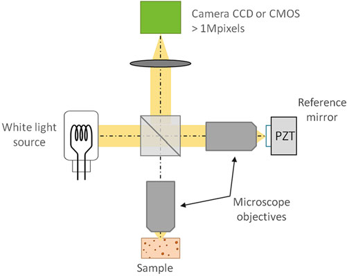
Fig. 1 Principle of the full-field OCM setup (Ref [1])
The basic experimental setup is a Michelson interferometer in the Linnik configuration. This configuration sets two identical microscope objectives in the sample and reference arm, respectively, which minimizes the path differences of two arms and maximizes the overlap between the interfering wavefronts.
A halogen lamp tungsten filament is adopted as the light source, and a Koehler illumination device helps generate a homogeneous distribution of light on the sample. ==The broadband incoherent source leads to a sub-micrometer sectioning capability and a small cross talk, due to its short spatial and temporal time.==
In this setup, to reduce surface reflection and to alleviate the aberrations (especially chromatic dispersion) introduced by surface irregularities, water or oil objectives are to be adopted.
2.1.1 Image Acquisition
2.1.2 Full-field OCM: Spatial Resolution and Sensitivity
Spatial resolution
In traditional OCT, low-NA lenses are used to obtain a large depth of field. However, it will in turn limit the transverse resolution.
Since FF-OCM generates en face images, high-NA objectives can be adopted, and thus the transverse resolution is not limited, i.e., 1 \rm{\mu m}.
As for the axial resolution of FF-OCM, it is still determined by the coherence length of the light source. The tungsten halogen lamp is a thermal light source, which creates smooth spectrum. It helps reduce the artifacts in the images. Additionally, the optical power is much more stable. The general formula of axial resolution using a Gaussian shape can be written in:
\Delta z = \frac{{2\ln 2}}{{n\pi }}\left( {\frac{{{\lambda ^2}}}{{\Delta \lambda }}} \right)When the central wavelength \lambda = 750 nm, the bandwidth {\Delta \lambda } = 300 nm, the refractive index n = 1.33, the theoretical axial resolution \Delta z will be 0.5 \rm{\mu m}.
Sensitivity
The amount of electrons stored during the acquisition time determines the optimum signal-to-noise ratio. There are some requirements for the camera:
- The images close to the saturation level must be shot noise limited.
- The full-well capacity (the largest charge that the camera can hold per pixel before saturation) must be as high as possible, i.e., 0.1-1 million off charges for silicon camera and about 1 million for InGaAs camera.
- For high SNR and in vivo operation, the frame rate should be higher than 150 frames/s.
- The pixel number should be large enough, i.e., 1 to 4 million for silicon camera and 0.25 to 0.5 million for InGaAs camera.
To further increase SNR, the reflectivity of the reference arm mirror must ensure the reference power equal or higher than all the incoherent light impinging on the detector.
2.2 FFOCM: The LLTech Research Setup
2.3 Improving the Available Depth using InGaAs Cameras
Increasing the imaging wavelength can improve the penetration and indium gallium arsenide (InGaAs) chips are used for detection in the range from 900 – 1,700 nm band.
When imaging at wavelength higher than 1.25 \rm{\mu m}, water absorption spectrum will be a major limitation. For silicone oil immersion, however, it allows a transmission from 0.9 to 1.6 $\rm{\mu m}$ except for two absorption bands near 1,160 nm and 1,400 nm.
3. Clinical Research Applications of FFFOCM
The studies should include the breast, skin, and brain.
4. Nondestructive Evaluation and FFOCM: From Electro-optics to Art materials
The high sensitivity of FFOCM (90 – 100 dB) makes it suitable for evaluation of layered materials in a noncontact way.
5. Multimode FFOCM: Fluorescence and Elasticity
Some other complementary information can be added to the FFOCM to enhance a morphological contrast.
5.1 FFOCM and Fluorescence Using Structural Illumination
FFOCM can not obtain the sectioning of cancer cells, so fluorescence imaging with structural illumination is adopted to supplement FFOCM, which contributes to a clearly visible imaging of cancer cell nuclei. Under this circumstance, high NA objectives should be used to achieve a sectioning of 1 \rm{\mu m}.
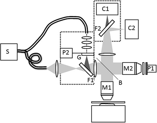
Fig.2 Setup used for simultaneous recording of structured illumination and FFOCM. S Xenon Source, C1 Fluorescence camera, C2 FFOCT camera, M1, M2 microscope objectives, P1, P2 piezoelectric modulators, F1, F2 filters, G Ronchi grid, B beamsplitter (Ref [2])
5.2 FFOCM Elasticity Map
6. Full-Field OCM for Endoscopy
The main application of endoscopic OCT is intravascular imaging for distinguishing various kinds of plaques. In addition, endoscopic OCT is also used for biopsy guidance with the help of needle probes. FFOCM shows the potential in this field due to its high axial and transverse resolution.
6.1 Principle: OCT Signal with Two Interferometers
The challenge faced with FFOCM when applied to endoscopy is maintaining the performance with a miniaturized, medically safe probe.
Typical experimental setup of endoscopic FFOCM uses two coupled interferometers with a probe: one is external to the probe, the other one at the distal end of the probe should be as simple as possible for in situ imaging.
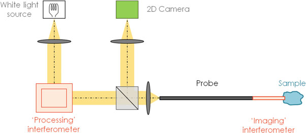
Fig. 3 Simplified principle of an endoscopic full-field OCM system with a common-path imaging interferometer (Ref [1])
If the probe includes an optical fiber, the bends or twists in the fiber will produce polarization differences of light in the sample and reference arms, which leads to signal distortion. On the contrary, the probe in Fig. 3 is not part of an interferometer arm and only used for transporting the images. Therefore, it is not sensitive to the surrounding changes and suitable for in situ imaging.
Here, a Xenon arc lamp is used as the white light source. Its spectrum is not as smooth as that of tungsten filament, but the power is much higher. Low temporal coherence contributes a good axial resolution, and the spatial incoherence helps enhance the sensitivity by reducing cross-talk effects. The processing interferometer is a Michelson-type one. The interference happens between the reference light reflected at the tip of the probe and the beam backscattered by tissues at different depths. To obtain the interference images from the background, a phase-shifting method is used in the processing interferometer first, and then a three-dimensional image can be built by performing one-dimensional depth scanning with the same interferometer.
Reference
[1] Optical Coherence Tomography Technology and Applications, p791-812
[2] [Multimodal full-field optical coherence tomography on biological tissue: toward all optical digital pathology](