The user manual for AQ6370D Optical Spectrum Analyzer can be found here. I will list some notes or confusions I met during reading this manual.
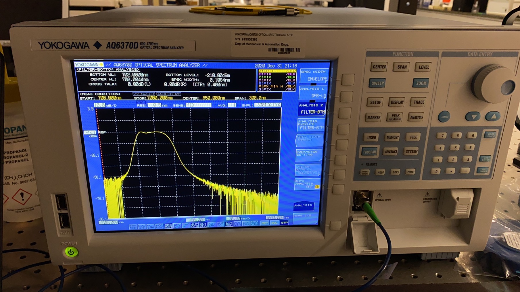
Fig.1. AQ6370D Optical Spectrum Analyzer.
1. The wavelength range of input light that can be auto-measured is 840–1670 nm.
This is the auto-measured wavelength range. During the measurement, span width , center wavelength, reference level, and resolution can be automatically set. After some auto-runs, these parameters will be decided. After that, you can choose “SINGLE”, and the sweep will be finished.
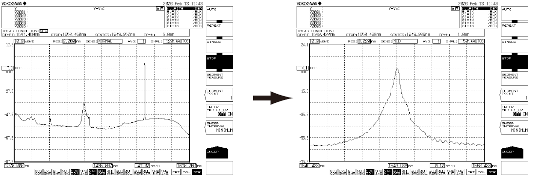
Fig.2. Screen after auto sweep starts and stops.
2. Set ANGLED if the optical fiber under test is APC (angle lap PC). Otherwise, set NORMAL.
Pay attention to the type of the optical patch cable that you use.
3. I just pass Alignment Adjustment, Wavelength Calibration, and Resolution Calibration, since it usually has been done before use. When it comes to calibration problem, I can refer to the relevant part.
4. With different fibers (SM, SI, GI), the obtainable resolutions are different.
The maximum wavelength resolution decreases when optical fibers with thicker core diameters are used (larger diameter, worse resolution). Refer to Section 3.9 Important Points During Measurement.
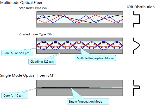
Fig.3. Differences between SM, GI and SI.
5. When the measurement sensitivity is set to NORMAL HOLD, the internal amplifier has a fixed gain.
When measurement sensitivity is set to NORMAL HOLD, if the level scale is set to 10 dB/DIV, the display would exceed the effective range. We recommend setting the level scale to 5 dB/DIV or less.
Under the measurement sensitivity settings NORMAL AUTO, MID, and HIGH 1 to 3, an automatic gain is used, permitting measurements over a wide level range through a single sweep. Select the appropriate sensitivity level based on the light reception level required for the particular measurement application.
For detail, refer to Section – Measurement Sensitivity and Vertical Axis Effective Range.
6. The display unit for the marker value (wavelength or frequency) can be set independently of the waveform display’s horizontal axis units (wavelength or frequency) that were specified using the HORIZON SCALE nm/THz soft key under SETUP. (Default: nm)
Y SCALE SETTING can be make in LEVEL.
7. LEVEL UNIT dBm dBm/nm
dBm: Power per resolution (absolute power)
dBm/nm: Power per 1 nm (power spectral density)
NOTICE: If power spectral density is assigned as the calculated waveform to Trace F and the unit is set to dBm/nm, Trace F enters FIX mode, and the waveform is no longer updated.
8. Automatically sets the peak level of the waveform measured every sweep
as the reference level.
Note that the operation is done during every sweep (Only works in “WTRITE” mode).
9. For THRESH 3dB center wavelength or center frequency, press the MEAN WL→CENTER soft key
Sets the average of two wavelengths falling below the threshold value (3 dB) from the waveform peak of the active trace to the center wavelength
Here the THRESH 3dB means:
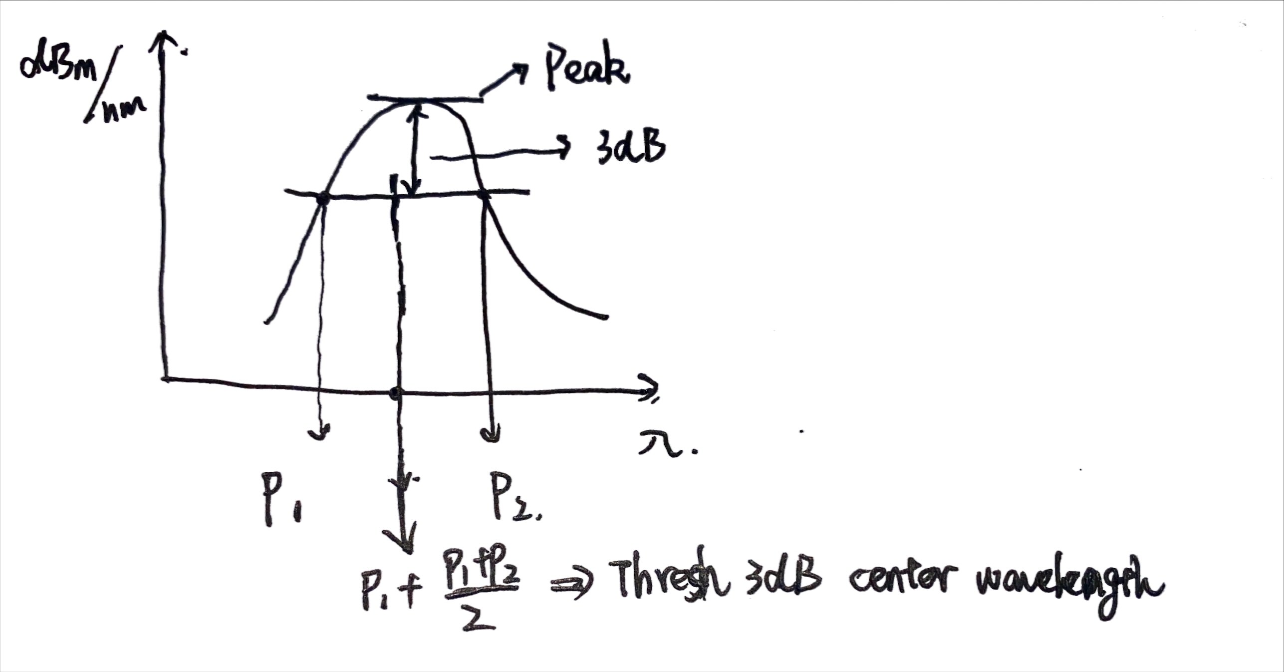
Fig.4. THRESH 3dB center wavelength.
10. VIEW→MEAS
This key is used to set the currently set ZOOM scale (ZOOM CENTER, ZOOM SPAN, ZOOM START, ZOOM STOP) as the measurement scale (CENTER, START, STOP, SPAN). When you press this key, the current waveform display scale is set as the measurement scale for the next sweep.
11. Δλ→ SPAN
Sets the sweep width as six times the spectrum width (threshold 20 dB ) of the active trace measurement waveform with the RMS method.(Still to be explored)
12. CHOP MODE
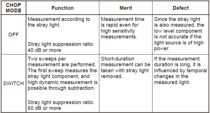
Fig.5. CHOP MODE Function List.
If stray light is likely to have a severe impact on measurements, the sensitivity can be set to MID or HIGH 1 to 3 and CHOP MODE can be set to SWITCH in order to reduce the effects of the stray light.
13. AVERAGE TIMES
Increasing the averaging times reduces the sweeping speed but the S/N improves.
14. SEGMENT MEASURE
You need to set SEGMENT POINT, for example, $n_s$. Every segment measure starts, $n_S$ points should be covered.
15. SWEEP INTERVAL
This key is used to set the time from one sweeping start to the next sweeping start during repeat sweeping
If the time required for sweeping is greater than the set time, the next sweeping is started immediately after sweeping ends.(Not sure whether it works or not)